
A Two-into-one Homemade Neon Dimmer
By Telford Dorr Number 17 - December 1995
By Telford Dorr Number 17 - December 1995
Sometimes you have to go backwards before you can go forwards. Trying to figure out the secret of dimming neon was like that. Here's the full story:
I had always heard that regular everyday incandescent-type light dimmers won't work with neon: however, being somewhat ofa nonbeliever in conventional wisdom, I decided to try it to find outfor sure. To make a long story short, the conventional wisdom is right. Regular dimmers don't work. Trust me.
It all started one day when the local hardware store had a sale on light dimmers, I think they were going for about three to fourbucks. These were the cheapie type with the round plastic knob which doubles as a push on/off switch.
To find out whether they would work as neon dimmers, I dragged the trusty 15kv/30 burn-in transformer up onto the bench,grabbed some miscellaneous tubes and jumper wires, and hooked the whole mess up.
After turning the dimmer up to full brightness, I plugged the creature in.
Initial success! The tubes lit to full brilliance. Things were looking really good, except that I then decided to turn the knob on thedimmer.
As I rotated the knob, the tubes started to dim slightly, and then suddenly the room was filled with weird flickering stroboscopic lighteffects, followed by darkness. All in a matter of seconds!
After that, no amount of wire-wiggling or knob-turning would restore the light. We're talking serious dead here. Giving up, I bypassed the dimmer, which erased the darkness. Glowing tubes indicated the failure wasn't the transformer, which only left thedimmer. Connecting the dimmer to a 100-watt light bulb yielded more darkness. Whatever died inside the dimmer was apparently going to stay dead.
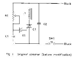
With nothing left to lose, I pried the cover off the dimmer to assess the damage. Reverse-engineering the circuit yielded Fig 1.
The circuit (before flameout) worked like this: device Q1 is a triac, which is a power-switching device. When triggered, it switches to afully conducting state, and stays that way until the current passingthrough it goes to zero. As it is connected to the alternating current, which changes direction 120 times a second, it will be turned off asoften. The trick to making it "dim" lies in how and when you turn it on. That task is left to components R1, C1, and D1.
Assume the following: the alternating voltage applied to the upper black wire in fig. 1 has just (timewise) crossed through zero and is increasing. Current starts to flow through pot R1 (the thing on the other end of the plastic knob) and starts charging up capacitor C1. As you turn the knob clockwise, you decrease the resistance of R1,causing C1 to charge faster. Turning counterclockwise increases the resistance, charging C1 slower. In other words, the setting of the knob controls how fast C1 charges.
C1 will charge up until it reaches the breakdown voltage of diode D1 (known as a diac). In my unit, this occurs around 20 volts. Once diode D1 reaches its breakdown point, it switches into aconducting mode, discharging C1 into triac Q1, turning it on (once on, power is no longer available to R1, keeping it from recharging C1 for the duration). This whole process repeats 120 times a second. Because the time delay caused by the charging of C1, the portion ofthe AC cycle over which Q1 conducts regulates the time periodduring which power is applied to the light bulb load, and thus itsbrightness.
So what, you ask. Why did the dimmer die, and what's this got to do with neon? The problem is this: with a light bulb as a load, once the triac is triggered on, voltage is applied to the bulb, whichimmediately conducts current. This current keeps the triac turned on until the current cycles to zero, some milliseconds later. The neon transformer, however, is a partially inductive load, not purelyresistive, like the light bulb. Applying voltage to an inductive load does not cause current to immediately flow - it takes a little time. The problem is, it takes too much time for C1, which uses up all its chargebefore the neon transformer gets going, and triac Q1 turns off again.This allows C1 to start charging again, during the same line voltagehalf-cycle! This process repeats, at breakneck speed, until the diac overheats and dies.
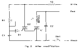
Herein lies the secret: What we need to do is somehow keep trigger current flowing into Q1 long enough for the neon transformerto get going, without overheating diode D1. I did this, as shown in Fig. 2.
Fortunately, when I was buying dimmers, I somehow had the sense to buy two of them. With my first dimmer lying in smoldering ruin on the bench, there was not much left to do but scrap it out forparts, the most useful being the still good triac, Q1.
Opening up the second dimmer, I mounted the salvaged triac, now known as Q2, onto its frame. (Note: at three bucks for a dimmer, it's probably the easiest way to get the triac.)
I rewired the dimmer as shown. Added resistor R2 is a 3500 ohm, 5 watt power resistor. I mounted it to the dimmer frame (as a heat sink) with a small bracket and some silicone grease. Wire the modified circuit EXACTLY as shown in Fig. 2. Reassemble the dimmer cover, using small screws in place of the original rivets orpins.
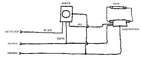
Note the colors of the new wires: they are critical, as there are now three of them. When connecting up the finished unit, make sure the white wire goes to neutral, as does one end of the neontransformer. The other end of the transformer goes to the red wire. The black wire goes to the hot AC supply. The switch MUST break the black wire!
The new circuit works like the original, with the following exceptions: (1) When D1 triggers, it turns on triac Q2. Because it has a resistive load (R2), it turns on immediately. Current though Q2, limited to a reasonable level by R2, continuously triggers triac Q1,giving the transformer enough time to start drawing power. Later, as the line voltage goes to zero, Q2 turns off, removing drive from Q1, which, because the transformer's inductive current time lag, turnsoff sometime after zero crossing.
Miscellaneous notes: the triacs used in dimmers seem to be internally insulated from their mounting tabs, allowing them to bedirectly attached to the (grounded) dimmer frame. Units purchased from Radio Shack and elsewhere may not be insulated, and thusrequire insulating mounting hardware. [Update 9/96: I have found that it is not necessary to mount Q2 to the dimmer frame, as it dissipates virtually no power. I now suspend the triac by it's leads. This makes the use of Radio Shack triacs viable.] In some (really cheap) dimmers, diode D1 is located inside the triac, in case you can't find the diodein your unit. In the modified circuit, this is OK for Q2 but not for Q1. If you use one of these combo units for Q2, eliminate diode D1 . In my dimmer, R1 was 250 ohms, C1 was 0.l uf, C2 (keeps line noise from false-triggering triac Ql) was 0.047 uf, L1 (value unknown, came with dimmer) helps keep switching noise from leaving the dimmer.
Application notes: (1) DO NOT use this circuit with high power factor type transformers or solid state type transformers. Itwon't work. (2) It sometimes helps to use a higher than normal transformer secondary voltage, if you're going to operate neon downto very low brightness levels. Experiment to see what you need. (3) Working with 120 VAC is dangerous. Use all possible caution. To limit flame and damage during bench testing, temporarily connect ahigh-wattage light bulb in series with your AC supply wire. This limits the maximum current flow in case of a short. (4) A final note: never work on the high-voltage wiring to your tubes on a dimmer-controlled setup, unless you KNOW the power is off. With a dimmer turned all the way down, your neon may not light up, but you will ifyou grab the wiring.
Well, there's the secret: buy two cheap dimmers, and make one neon dimmer. It's easy when you know how (and why).
Copyright 1989 THE NEON NEWS
Published by Ted Persig & Val CrawfordEmail:
crawford@hawaii.net